 Electronics
 Concept
Concepts involve the working of the joystick module and the pushbutton trigger. Apart from that, it is just coding and using a special library to do the job.
Components required
- Electronics club custom development board
- HW-504 joystick module
- Jumper wires
Libraries required
- BleKeyboard.h
BleKeyboard.h is the header file which is used to provide keystrokes to the laptop via bluetooth. However, this library is not directly installable through the library mananger. Instead the .zip file must be downloaded and then must be manually added. Follow this procedure:
- Download the latest release of ESP32-BLE-Keyboard.zip from this github link: T-vK/ESP32-BLE-Keyboard.
- Open you Arduino IDE and choose Sketch/Include Library/Add .ZIP Library and select the .zip file you downloaded.
The library is now installed and can be used.
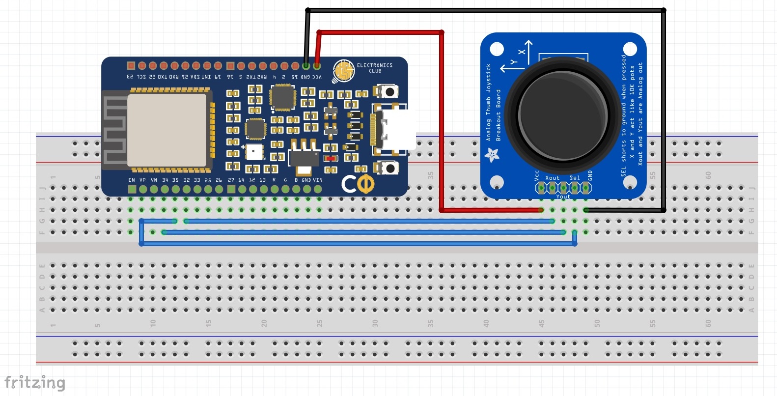
Schematic
Make the following connections:
- GND of HW-504 <-> GND of Dev board
- +5V of HW-504 <-> Vcc(3.3V) of Dev board
- VRx of HW-504 <-> Pin 32 of Dev board
- VRy of HW-504 <-> Pin 34 of Dev board
- SW of HW-504 <-> Pin 35 of Dev board
Important note: The ADC2 pins won't work together with the BLE library. So they can't be used as the reading pins for VRx, VRy and SW. Instead use ADC1 pins (I used pins 32, 34 and 35 which are ADC1 pins).
Working of the joystick
The analog joystick basically works based on the Gimbal mechanism. Beneath the stick, there is a rod which is placed on two U-shaped arch like structures. These U-shaped structures are actually 10K potentiometers and when the stick is moved, the rod also moves which generates an electric signal. This signal value depends on the degree to which the stick is moved. The following images will give an idea:
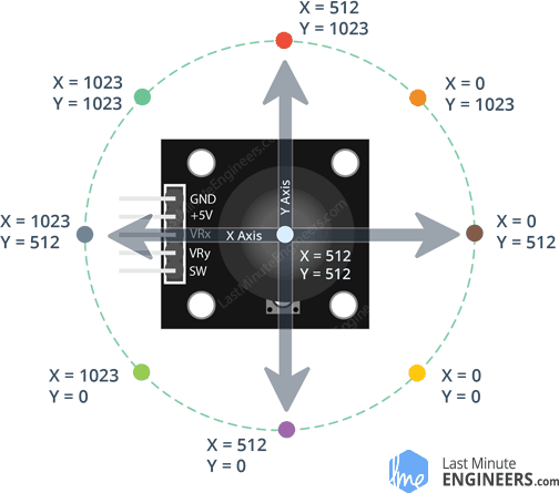
The values given in the second image need not be the same for everyone. For example, in my case, the values range from 0 to 4095 because the Dev board has its ADC bit resolution as 12 bits. Also, the X-value became zero when the analog stick was moved left and Y-value became zero when the stick was moved up. Basically the values given in the image are flipped with respect to the X=Y line in my case and 1024 is scaled upto 4096. So, one hint is when you do this project on your own, first check what the X, Y values are by reading the VRx, VRy values and printing them on the serial monitor. Once, you get to know which position correspond to which range of values, you can accordingly code to provide the correct strokes. Also, decide the X, Y axes before writing the code (I took the X-axis as the horizontal axis and Y-axis as the vertical aixs with respect to the second image)
Code:
#include <BleKeyboard.h>

BleKeyboard Key("Temp");
/*
Replace Temp with the name you want to provide for the bluetooth of the board.
That name will appear in the devices list when you switch on the
laptop's bluetooth. Also, the board must be paired for sending the keystrokes.
*/

boolean state = !false;

void setup() {
  Serial.begin(9600);
  Key.begin();
}

void loop() {

  int x = analogRead(32);
  int y = analogRead(34);
  /*
  int trig = analogRead(35);

  if(trig==0){
    state = (!state);
  }
  */
  Serial.println(x);
  Serial.println(y);
  //Serial.println(trig);
  Serial.println(state);
  Serial.println("------------------------");

  if(Key.isConnected()){
    if(state==true){
      if(x>=1024 && x<=3072 && y==0){
        Key.releaseAll();
        Key.press('W');
      }
      else if(y>=1024 && y<=3072 && x==0){
        Key.releaseAll();
        Key.press('A');
      }
      else if(x>=1024 && x<=3072 && y==4095){
        Key.releaseAll();
        Key.press('S');
      }
      else if(y>=1024 && y<=3072 && x==4095){
        Key.releaseAll();
        Key.press('D');
      }
      else if(x<1024 && y<1024){
        Key.releaseAll();
        Key.press('W');
        Key.press('A');
      }
      else if(x<1024 && y>3072){
        Key.releaseAll();
        Key.press('S');
        Key.press('A');
      }
      else if(x>3072 && y>3072){
        Key.releaseAll();
        Key.press('S');
        Key.press('D');
      }
      else if(x>3072 && y<1024){
        Key.releaseAll();
        Key.press('W');
        Key.press('D');
      }
      else{
        Key.releaseAll();
      }
    }
  }
  else{
    Serial.println("Bluetooth not connected");
  }
  delay(1);
}
Important note: Connecting the circuit to laptop is not a necessity since we are sending the strokes via bluetooth. Only at the initial stage, we must connect the board to the laptop to upload the code. Later we can remove this connection and can power the board via a normal power adapter. Also, upload the code while there are no external connections. Once that is done, make the external connections.
Possible changes: The code provides keystrokes to the computer. Hence, if not controlled properly, the code may provide random keystrokes and can create a mess. So ensure that a control signal (Say a pushbutton) is used to enable and disable the code.
I used the in-built pushbutton of the HW-504 as the control signal.
/*
int trig = analogRead(35);

if(trig==0){
 state = (!state);
}
*/
This commented code snippet pertains to it. Uncomment this snippet in the main code to use the inbuilt pushbutton as the control signal. Also, initialise the variable state with boolean value "false" (Remove the ! symbol in the line that declares the variable 'State')
Sometimes, the inbuilt pushbutton may behave weirdly because of the associated X,Y movements. Hence, it's better to use an external pushbutton as the control signal. The only change you'll need to make to the schematic is to remove the SW <-> Pin 35 connection and provide the external pushbutton input to pin 35. The schematic is given below:
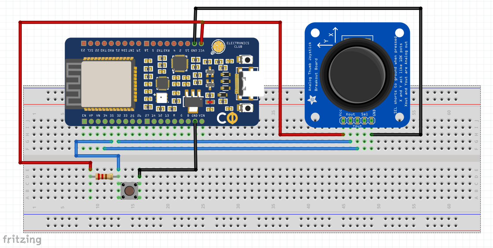
(The control signal is pulled up so that it will be a non-zero signal by default and will become 0 only when the button is pushed)
3 . For smooth functioning of the joystick, we need to keep the sampling time as small as possible. That's why I provided a delay of 1 ms. However, having such a small delay means the system will sample the inputs 1000 times per second and hence, the pushbutton control signal may not work properly. Let's say the button is pressed for 0.52 seconds. Hence, the control signal will be zero for 520 ms meaning the system will sample that many 0 value for pin 35. Since this value is even, the final value of the "State" variable will still remain false. Essentially, the pushbutton didn't serve it's purpose. Hence, it's better to use a two-contact switch here and using it as a control signal instead.
Follow up Problem statement
As a follow up problem statement, learn how you can send the keystrokes through the USB instead of bluetooth using the BLE library. Note that for this to be done, the circuit must be powered using your laptop. Also, learn how you can do the same using IMU instead of the joystick module. The values obtained from IMU maybe noisy and hence, the WASD control may not be exactly matched but still it's a good learning outcome.
References
Demonstration video: